Integrated energy storage refers to storing electrical energy in the energy storage system, and performing operations such as boosting, discharging, and inverting the electrical energy through batteries or inverters to achieve the purpose of energy storage.
In principle, the integrated energy storage system can be divided into two forms, one is the integrated energy storage system (Fabless) with the battery as the main body; the other is the integrated energy storage device with the inverter as the main body .

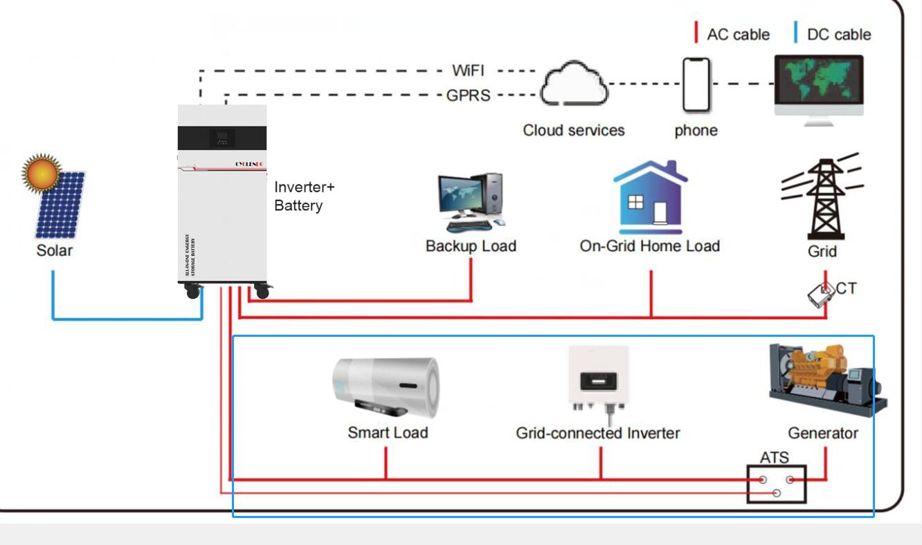
Let's take a look at the structure of the all-in-one battery:
The inverter is an important device in the energy storage system. Its function is to convert the alternating current in the grid into direct current, and perform operations such as filtering, boosting, and inverting inside the inverter to release electric energy.
An integrated energy storage system generally consists of a rectifier, an inverter and a battery.
From the perspective of the structure of the inverter, the integrated energy storage system is mainly composed of a DC power supply, a boost rectifier converter, an inverter and a management unit.
Due to the intermittent and random characteristics of photovoltaic power generation, photovoltaic modules themselves have no power generation capacity (the so-called "self-consumption"), so photovoltaic modules generally need to be equipped with inverters.

1. Battery: Single battery capacity (Ah): rated voltage - rated current, battery pack with a capacity of 1 kW.
2. The controller (CAN-BUS) is responsible for sending and receiving, displaying and controlling signals between modules.
3. Power: The controller is a single-channel inverter in parallel mode, that is, each inverter has its own independent output voltage and current waveform, and the controller can generate corresponding output voltage and current waveforms according to its own control algorithm, and Output via relay.
4. Control scheme: A number of advanced control algorithms are adopted, which can quickly respond to the actual electricity demand of users, and realize load short circuit, overcurrent protection and charging time delay protection on the user side.
5. The communication adopts Ethernet technology, and the data transmission is carried out at a rate of 100 Mbps.

Mainly used for communication between the inverter and the battery,
communicate through the wireless module,
Can be customized according to user needs, such as RS485, CAN, RS232, etc.;
Support multi-machine parallel connection to realize simultaneous operation of large-capacity energy storage units;
With RS232/485 serial port communication function, it can monitor the battery remotely.

Switching devices are full bridge and half bridge etc.
The functions of the isolating switch are: 1. When the voltage or frequency of the AC grid changes, it can automatically switch to a safe, reliable and high-efficiency DC power supply; 2. When the voltage or frequency of the grid changes, it can cut off the power supply of the AC circuit system in time , to prevent overvoltage in the power grid; 3. The switching device maintains enough time between opening and closing to ensure that the current is quickly broken without endangering personal safety; 4. When there is a possibility of major interference to the system (such as: In case of short circuit and overcurrent), the DC circuit can be automatically cut off.
5. Protection device
The protection functions of the inverter mainly include protection functions such as overvoltage, phase loss, overcurrent, and overload, as well as overtemperature and overdischarge protection functions at the battery side.
The realization of the protection function is mainly realized by the inverter and the protection device, mainly through the software control module or the hardware circuit.
In order to prevent faults or abnormal situations, a corresponding fault diagnosis unit, such as an electronic fault diagnosis instrument (EDA), should be installed in the inverter to monitor and diagnose the inverter online.